The original drone stays unchanged beside this separate variant. The v2 electronics now sit on an independent structural tray at the existing floor datum. The Pi standoffs, Pixhawk bridge and camera brackets are joined to that tray; removing the shell does not release their attachment to the frame. Four M2×12 screws clamp the tray and spacers to frame-retained inserts. The removable wall uses separate M2×8 screws and captive nuts. Four short bridges connect adjacent motor guards. Rounded arms, low guard walls, visible three-blade props and the shallow battery saddle are retained.
Status: geometry-checked prototype, not a released flight build. 37 geometry checks pass. The stated 3.8–4:1 target is NOT achieved by the selected 1404 reference. No aerodynamic, impact, thermal or flight qualification is claimed. The original 1404 constraint is retained pending the propulsion decision.
| Item | Quantity | Model and interface |
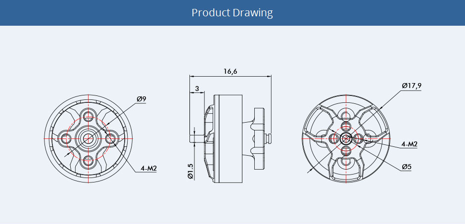
| Motor | 4 | T-Motor F1404 4600KV, 3–4S, 9.34 g each. Ø17.9 mm, 16.6 mm overall, Ø1.5 × 3 mm prop stub, four M2 on Ø9 mm circle; prop fastening on Ø5 mm circle. |
| Prop | 4 | HQProp T3×3×3, 2 CW + 2 CCW, 76.2 mm diameter, Ø9.8 × 4.9 mm hub, 1.5 mm centre and M2 T-mount; 1.48 g each. Buy these; the blade STLs are display references, not manufacturing files. |
| Battery | 1 | GNB GNB11004S140A, standard 14.8 V 4S 1100 mAh LiPo, XT60, 82 × 39 × 25 mm, 141 ±4 g. This replaces the unsourced 70 × 38 × 25 / 115 g assumption. |
| Motor screws | 16 | M2×4 shown through the 2 mm plate. Check supplied motor screw thread depth before use. |
| Prop screws | 8 | M2×7 shown through the 4.9 mm hub, giving 2.1 mm nominal engagement. Length is provisional until actual blind-hole depth is checked. |
| Carrier screws / nuts | 4 / 4 | M2×16 / M2 nuts, holding the upper plate through the four original central posts. |
| Payload screws / inserts / spacers | 4 each | M2×12 screws, M2×3 heatset inserts and 3 mm spacers. The previous M2×8 screws are too short for the corrected frame attachment. Insert supplier/pilot bore and installation process require qualification. |
| Removable lower shell screws / nuts | 4 / 4 | M2×8 screws inserted upward through the tray; standard M2 hex nuts seated in top-loaded hex pockets in the shell. These are separate from the four payload-to-frame screws. |
| Battery restraint | 2 + 1 | 10 mm wide hook-and-loop straps; 80 × 38 × 2 mm compliant pad. Modelled straps contact the battery; verify buckle placement and retention on the sample pack. |
Sources: T-Motor dimensions and test table, manufacturer's dimensioned drawing, distributor mirror, HQProp product, GNB battery specification.
Only published interfaces/envelopes are used as hardware dimensions. Unspecified bell contours, internal stator details, blade surfaces and screw threads are representative; a rendered fit is not a substitute for checking delivered parts. The motor's internal 2 mm shaft specification must not be confused with its 1.5 mm exposed prop stub.
- Upper plate: 2 mm carbon laminate, z47–49. Prototype DXF is a section of the validated mesh; it uses polygonal approximations of holes. Supplier must check actual stock thickness, hole tolerance, edge finish and strength before manufacture.
- Guard carrier, bridges and saddle: one joined prototype mesh. Four broad bridges join the front, rear, left and right pairs of rings at z28–36. Their inner edges follow the 79 mm guard bores. Mass assumes solid PA12 at 1.01 g/cm³. SLS PA12 is the proposed prototyping process; no print orientation or FDM substitute has been structurally qualified. Connectivity checks do not measure the stiffness gain.
- Motor/guard centres: X/Y = ±41.5 mm, measured from the aircraft centre. Adjacent centres are 83 mm, not 82 mm. Ø82 guards have a 1 mm nominal gap; small outer datum bumpers give a 166 mm footprint.
- Guard inner diameter: at least 79 mm; 76.2 mm nominal rotor envelopes leave 1.4 mm radial clearance. Ring walls occupy z27–37; inner mounting risers reach z47. The independent tray underside starts at z52.
- Each motor mounts inverted below the upper plate at z47; a Ø5.4 mm central plate relief clears its rear bearing feature. No arm continues beyond its motor pad.
- Battery pocket: 86 × 43 mm, 2 mm clearance per side around the specified pack. Pad supports its underside; straps clamp it. Cell body z−5.5…19.5, prop hub z30…34.9. Flexible battery leads and connector tolerances are not included in the manufacturer's cell envelope.
- Payload mounts remain at X=±13, Y=±22.8 mm. Four Ø9 mm carrier bosses occupy z42–47; matching carbon pads occupy z47–49 and fully support the Ø6 mm spacers at z49–52. Housing floor: z52–55. M2×12 screw shafts run from z43 to the head seat at z55; each engages the full 3 mm insert at z43.5–46.5. The inserts retain their original shape but move down into the frame. The four central carrier holes remain at radius 18.03125 mm on the X/Y axes.
- The insert pockets represent the installed insert envelope, not a qualified heat-setting pilot bore. Before manufacturing the carrier, select the actual M2×3 insert and replace the pocket preparation with its supplier-specified pilot, then validate installation and pull-out strength. The geometry export does not qualify that manufacturing detail.
- Independent tray: the original shaped floor at z52–55, with full landings under all four Pi standoffs. The Pi standoffs, Pixhawk support bridge and camera bracket feet form one connected prototype export with the tray. The inherited 2 mm camera bracket gaps are closed; reference boards, screws and wires receive reliefs with a 0.2 mm lateral allowance, preserving seating heights. ESC grommets have shallow seating recesses. Board geometry, component retention, threaded interfaces and cable restraint remain prototype details requiring checks against the delivered electronics; the open configuration is not a released flight build.
- Removable wall: starts at z55.3, leaving a 0.3 mm cosmetic seam above the tray. Its four boss feet extend down to z55 and seat directly on the tray, so the screws clamp solid faces without closing that seam. Shell screw centres are (−30,−41.5), (+30,−41.5), (−34,+31.5), (+34,+31.5) mm. Screw shafts run z52–60; captive nuts occupy z57.5–59.1. The regulator-to-Pi cable route moves 1 mm inward in X/Y to clear an inherited service-cover boss.
- Aircraft envelope: 166.0 × 166.0 × 119.4 mm, within the stated 250 mm cube. The two-aircraft comparison itself is wider than that cube.
1. Compare the delivered motors, props and battery against the listed interfaces. Resolve any mismatch before ordering fabricated parts. Confirm the motor/prop screw depths with the actual motor, including that screws cannot contact windings or rotating parts.
2. Resolve the insert pilot preparation described above, then make and inspect the carrier/saddle prototype and carbon upper plate. Install the four payload inserts in the carrier bosses before fitting the carbon plate; verify their top faces at z46.5 and retention. Check carrier continuity, guard flex and carbon edges; a mesh pass does not establish crash strength.
3. Fit each motor below its carbon pad using four M2 screws. The stationary mount touches the underside at z47; the rear bearing clears the centre opening. The bell must turn freely without touching the plate.
4. Fit the carbon plate to the carrier posts using four M2×16 screws and nuts. Seat each 3 mm payload spacer on its carbon pad, place the independent tray on the spacers and attach with four M2×12 screws. Check all four seats, actual thread engagement, insert retention and fastener access. Mount and secure the electronics on the tray supports, including the isolated Pixhawk. Use the viewer's Payload mounts inspection view to see the frame attachment.
5. Thread both straps through their saddle slots. Place the 2 mm pad, then the battery centrally. Tighten the straps around the battery and saddle, keeping all cables and the balance connector out of every rotor sweep. The specified pack uses XT60; the copied payload's provisional XT30 power interface needs a properly rated redesign before connection.
6. Complete and verify the electrical integration with props removed. The inherited generic 35 A ESC must be identified and rated per channel; 35 A total is insufficient for the cited maximum. Select and validate the Pi 5 power regulator, input wiring, connectors, fuse/protection and cooling. The retained provisional regulator is not an approved 5 V/5 A design.
7. Configure the controller's actual motor ordering and verify each physical motor's direction. CAD quadrant names are not firmware motor numbers. Fit the purchased props with their lifting face upward even though the motors are inverted. Two opposite corners share a direction. Check full 360° clearance and guard deflection around every prop.
8. Before free flight, measure finished mass/CG, guarded thrust, supply sag, ESC/motor temperatures, Pi supply stability and vibration; then conduct a controlled restrained/low-hover commissioning procedure with an experienced multirotor builder. Set failsafes and validate control mapping. Do not infer flight readiness from green geometry checks.
Rotation layout, viewed from above (+Z), with FRONT toward −Y:
| Position | Centre (mm) | Rotation |
| Front left | −41.5, −41.5 | CCW |
| Front right | +41.5, −41.5 | CW |
| Rear left | −41.5, +41.5 | CW |
| Rear right | +41.5, +41.5 | CCW |
Use V2 shell off in the comparison. The tray, Pi standoffs, controller bridge, camera supports, payload screws and spacers all remain. Only the lower wall, upper service cover, gasket and their dedicated fasteners disappear. The original drone is unaffected by this control.
For removal: power down, remove the upper service-cover screws, lift the cover and gasket, remove the four upward-facing M2×8 shell screws from beneath the tray, retain their nuts, then lift the lower wall clear of the electronics. Leave the four M2×12 payload/frame screws fitted. Fit in reverse order; load the shell nuts into their pockets before refitting the lid. The shell has no electrical attachments and does not carry the electronics supports. Shell lift clearance is checked at 1 mm intervals over 60 mm of travel; real connectors and flexible wiring must also be checked.
The open configuration still needs secure retention of every board, camera, antenna and cable, suitable controller protection, and vibration/thermal/flight testing. This change establishes the independent structural support; it does not qualify the inherited provisional electronics integration.
Estimated enclosed AUW 524 g assumes the user-provided 275 g payload includes its housing, plus 36.3 g carrier/bridges/saddle, 11.4 g carbon, the purchased components above, a 15 g hardware/pad/strap/wiring allowance and 2 g for shell fasteners. Payload plastic changes use an assumed 1.27 g/cm³. This is not a measured mass.
The shell-off estimate is 457 g, or 2.72:1 using the same ideal bench thrust. It subtracts the modelled removable plastic volume at the assumed density and 2 g of shell hardware. Actual printed mass and the user-supplied payload estimate must be weighed before treating this difference as achieved.
The F1404 4600KV/HQ3×3×3 manufacturer bench result is 310.57 g at 15.64 V and 20.23 A per motor. Four give 1,242 g ideal combined static thrust, or 2.37:1 at the estimated mass, before the effects of the complete guards, housing, wiring and battery sag. Four channels could draw about 81 A before avionics. No duct thrust benefit is assumed.
Reaching 3.8:1 at this mass requires roughly 498 g per motor. A stronger documented 3-inch combination or a larger guarded rotor system is required; merely shrinking the battery drawing cannot fix this. Motor selection may require new pads and a different shaft/hub interface. The current drawing preserves the requested 1404 mount instead of silently substituting incompatible parts.
- fabrication/: joined carrier/bridges/saddle prototype STL, 2 mm carbon plate prototype DXF/reference STL, independent tray with joined supports, and removable lower shell prototype STL. The retained upper cover and gasket also have individual reference meshes in parts/.
- parts/, atlas.stl, atlas.json, assets/: refreshed individual meshes and atlas, including purchased hardware visualization. Do not print propeller or motor meshes for flight use.
- ava-v2-assembly.stl: complete revised display assembly; ava-v2-open-assembly.stl: shell-off display assembly; existing-themis-assembly.stl: unchanged original.
- Complete assembly STLs contain contacting reference components and are for viewing, not manufacturing or single-solid import. Use the closed individual component meshes, atlas or joined fabrication/ prototypes for downstream CAD work.
- design-graph.json, design-spec.json, source/: editable graph, parameter definitions and source snapshots. Run the maintained source from the neighbouring Dingcad workspace (npm run build:v2, npm run validate:v2), which provides the original mesh assets.
- validation.json, payload-mount-validation.json, open-configuration-validation.json, part-measurements.json, mass-budget.json: measured geometry checks, four-point attachment support/engagement, independent tray and bridge connectivity, and explicitly estimated mass/performance. Individual payload screw, spacer, tray, bridge and shell STLs are included in parts/ and the atlas.
- preview.html, preview-geometry.json, viewer/: comparison viewer and geometry. Serve this directory over HTTP; browser module loading does not work reliably from file://.
All coordinates are millimetres. Part STLs use local X=Y=0; the website adds X=650 mm for v2, while the original sits at X=390 mm. Atlas parts additionally have the offsets listed in atlas.json. Display-STL simplification tolerance is 0.001 mm. The public viewer has direct pointer panning without the previous long damping tail; Dingcad's exact internal camera constants are not exposed in its compiled runtime.